In Situ Bio-Enhanced Thermal Remediation - Part 1
By: CascadeWelcome back to another of our featured webinar breakdown blogs. This post is Part 1 of In Situ Bio-Enhanced Thermal Remediation. In this post, we provide an overview of the dominant in situ thermal remediation or ISTR technologies available in the marketplace today. We also touch on the ways in which each technology functions including their inherent strengths and limitations. Stay tuned for part 2 where we’ll briefly cover how these different ISTR technologies can be combined with each other to engineer around complex or otherwise limiting site features.
WHAT ARE THE DIFFERENT ISTR TECHNOLOGIES AVAILABLE?
Thermal Conduction Heating (TCH) – 20 to 400 Degrees Celsius
TCH uses circuits of heaters which generate and propagate heat in the subsurface through thermal conduction, propagating heat radially outward from the heaters to the surrounding soil. TCH can be useful in very low temp applications, like a 30⁰C operating temperature, wherein the strategy is to target subsurface temperature ranges that maximize heat enhanced biodegradation and free product removal. But, it’s just as useful all the way to high temp applications reaching 400⁰C for creosote and MGP Sites, or applications like the in situ destruction of dioxin, such as at the Danang project in Vietnam that TerraTherm is currently leading.
Thermal conductivity of soil varies insignificantly across a site, which means that this wide range of temperatures can be realized with a great deal of control and precision.
Steam Enhanced Extraction - 100 Degrees Celsius
SEE involves the injection of steam at variable pressures and flow rates through screened injection wells placed throughout a treatment volume. This is often coupled with MPE or GW extraction wells to ensure hydraulic control and to mitigate any off-site migration of contaminants. This technology is ideal for remediation of VOCs and free product in highly transmissive intervals that feature high permeability lithology and groundwater flow rates that would otherwise render ERH or TCH impossible.
However, SEE is limited to 100⁰C applications and the site conditions that permit SEE are rather specific.
Electrical Resistance Heating – 20 to 100 Degrees Celsius
ERH uses electrodes, placed in 3-phase or 6-phase arrays, to force a controlled current through the subsurface, propagating from electrode to electrode. Soil between electrodes resists that current flow, and electricity is transferred to heat energy as the soil temperature increases. ERH is an effective option for low to moderate temperature applications up to ~100⁰C . ERH can be applied with a great degree of control especially for low temp applications as it does not generate “hot spots” around the well. ERH is also a highly effective ISTR technology in saturated zones below the water table and in tight lithologies such as clays and silts.
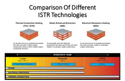
*Visual Representation of the three main ISTR technologies
WHAT ARE THE FOUR STEPS OF THE ISTR PROCESS?
All three of the ISTR technologies, aside from heat generation and propagation mechanisms, rely on the same basic four steps:
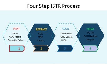
Representative of TCH and ERH – SEE is slightly different as a boiler is used to generate the energy being input into the subsurface rather than electrical power.
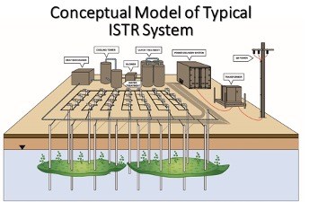
The first step is the power. An ISTR project “power drop” can range anywhere from a 250-amp 480V service all the way up through a 6,000-amp 480V 3-phase (or greater) service capable of providing 6,000-kVA of power. The power drop and demands ultimately depend on the size of the ISTR treatment volume and the power control units that will need to be deployed to a given site.
From the PDS, power is delivered to the wellfield, heating up the site subsurface and generating contaminant vapors and steam – which are recovered through a network of vapor recovery wells. Free product and groundwater may be recovered as well if MPE is a part of the operational strategy. All process fluids are conveyed to above-ground treatment system, where process streams are treated before discharge or disposal.
Additional site features at a typical ISTR site include:
- Insulting Plenum/Vapor Cap to help vapor control, retain heat, and mitigate potential contaminant recondensation.
- A network of TMPs and VMPs to monitor subsurface temperature and pressure, in order to monitor system and remediation progress.
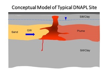
A quick glance at a Conceptual model of a typical ISTR Site featuring a DNAPL plume.
Typically these sites consist of tight lithology throughout the treatment volume or, clays and silts above and below an interval exhibiting higher hydraulic conductivity, usually featuring sands or gravels.
Product accumulation occurs at the interface between the higher conductivity interval and the semi-confining clay, or bedrock layer below. If the lower unit is bedrock, TCH becomes the preferred ISTR technology as its heat generation and propagation mechanisms lend itself to heating materials with low permeability low pore water content, which ERH can struggle with. Typically, ERH becomes rendered ineffective when the electrical resistivity of the lithology is greater than 500 ohm-m, at which point TCH becomes the only viable option.
Additionally, if the sand/gravel layer exhibits groundwater flow rates of higher than ~1-ft/day, a SEE component is often needed to supplement an EHR or TCH system design.
WHAT ARE SOME COMBINED THERMAL REMEDIATION TECHNOLOGY APPROACHES?
Sometimes one technology is not enough, in which case we can combine different ISTR technologies. Here are the combinations we’ll cover below:
- Combined ISTR Technologies
- TCH-SEE
- ERH-SEE
- ERH-TCH
- ISTR- Biodegradation (Heat Enhanced Bio)
- Post ISTR Bio-Polishing
- Low Temp ISTR- Heat Enhanced Bio
- ISTR Source-Enhanced Bio Downgradient Plume
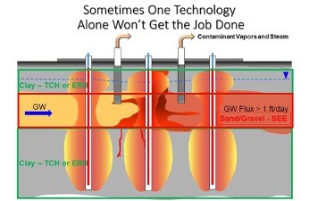
As the above graphic illustrates: ISTD and ERH are able to deliver enough energy to effectively heat zones where GW flux is < 1 ft/day
*If GW flux is too high, poor heating and inability to uniformly reach target temperature
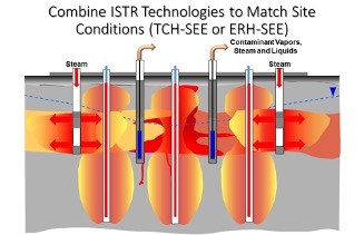
Steam can be combined with these technologies to address permeable zones
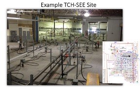
Example: Large site located in St. Pete where ISTD and SEE were combined
TTZ: 90,000 ft2, mostly inside a building, to depths of 55 ft
450 heater wells
36 SIWs
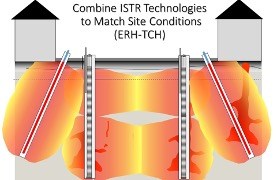
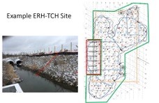
Example: Anderson, IN Site
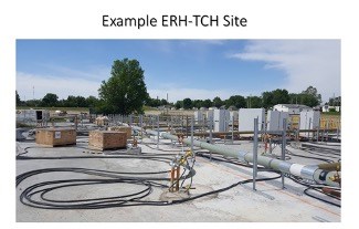
Combined TCH-ERH Project.
TCH heater cans were installed on the sloped area. TCH was chosen for this area, as the heat generation and propagation mechanisms lend themselves to angled or horizontal applications. ERH on the other hand has to be phased in an array and communication between electrodes in angled or horizontal installations often engender difficulties in homogenous heating.
The electrode field is comprised of nearly 200-electrodes and is augmented with the addition of the 9 TCH heater cans in the sloped area.
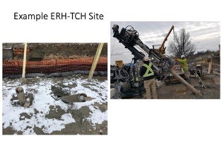
Here is an example of an angled TCH heater can being installed in really close proximity to an electrode for the ERH field; just shows how close they can be installed to one another with minimal impacts on the technology.
There you have it. Hopefully now you have a high level understanding of the various In Situ Thermal Remediation technologies available.
And of course, read part 2 of our In Situ Thermal Remediation blog where we’ll cover the various ways in which these technologies can be combined to mitigate specific site challenges while still meeting project goals.
